

| My name is Yuriy, I am a
surveyor. I started to develop my own gps receiver because of this post,
which I encountered accidentally on a surveyors message board. As
you will see this post inspired me a lot :). Partly because I got sick
and
tired of winter surveying in Alberta, partly because it seemed like
easy
to built your own gps at low cost and it looked like a good hobby. This has been my hobby for last 7 years, and it turned out not to be so easy to develop the system and not cheap either. Every summer, during system development, I was dreaming about fall to come, the time I was moving to Canada for work. Now walking in deep snow, cutting trees down the boundary lines was a good thing because I did not have to torture myself with the system development. Eventually I build 14 receivers and the only thing left do to is to certify the units and register a company or become a sole proprietor. It is strange that for some reason I do not care if this hobby materializes as business. The only thing that brings me peace of mind is that I am done with it. After all surveying is more enjoyable lifestyle than sitting at home soldering wires, casting plastic enclosures, staring at the pc screen all the time. Bellow is the entire story from the very beginning: |
| I purchased an oem gps
module,
voltage regulator, signal level converter, as it was specified in the
message and started to experiment. I had no knowledge in electronics so
I started from scratch. Most of the information about how electronics
components work I took from data sheets, wikipedia and google.
Eventually I connected the module to a pc and when I saw first several
lines of binary messages on terminal screen I thought I achieved
something extraordinary :), for me that was quite a step. |
|
|
|
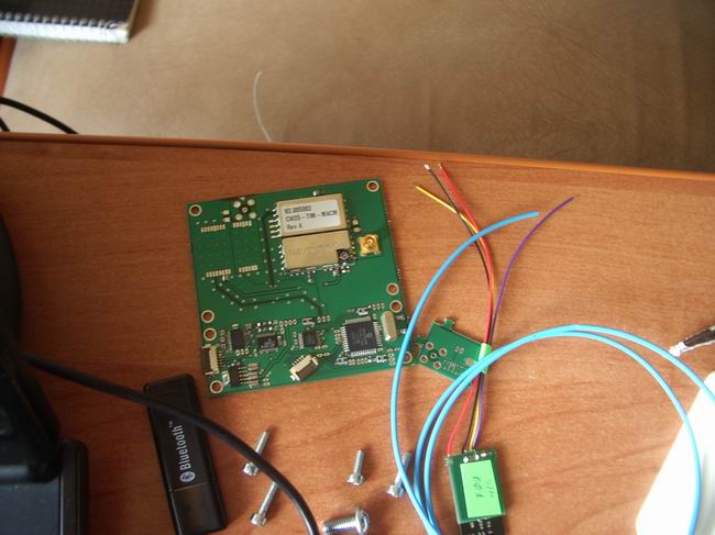
| oem board (left) transceiver with caps and DB9 connector (right) | All
in a metallic box |
| My
next step was to write a program that would control gps, show info
about tracked satellites, and write data to hard disk. After that I had
to write a program that would generate RINEX files from the
data
stored on disk. After I spent entire summer learning C++
programming and serial communications I developed a data collection
program and RINEX converter. Parsing binary files and forming RINEX
files turned out to be a very laborious task. I spent a lot of time
studying GPS interface manual before I decoded ephemeris. Eventually a
had a system that I could survey with: |
|
 |
 |
| data collection program | |
| In
order to get rid of a laptop, which was part of my system, I had to
build a compact circuit that would control gps, write data to a memory
card, signal system status with LEDs, monitor batteries charge
level etc. I found out about microcontrollers, purchased a development
kit and a compiler and started to learn this new
world. I added to my system a chip that monitors
batteries
charge level, checks
power button, signal level converter, signal lines switch chip etc.
When I
build my first prototype on a card board and it worked that was quite a
feeling:) Turning a cardboard into a pcb was not easy either. Found program called eagle, learned how to use it, designed PCBs, eventually generated gerber files, sent them the to the factory and in a few weeks received my PCBs with components soldered. Because of my numerous errors each version did not work properly. Every year I was developing a new version. Only third version works fine. |
|
 |
 |
| 1. Development kit | 2.
First cardboard prototype, no laptop is needed |
 |
 |
| 3. First pcb version, (top two boards) | 4.
Second version |
 |
|
| 5. Third version, all on one board | |
| Now I wanted to make a nice
plastic enclosure. So first I had to design it. I learned
3d commands and drafted pcbs then 6 batteries underneath, and than
wrapped everything with ellipsoid shaped surface. It took
me 1.5
month. Now I had to materialize this enclosure in real world. I was going to cut the model in thin layers, print each layer on a plastic sheet, cut each sheet along printed lines and clue cutouts together building up real enclosure - that was my crazy idea. But I was lucky to find out that 3d printers exist :). That was quite a discovery for me. I found several vendors, sent them my files and received a few quotes. Ordered and in a few weeks I received my materialized parts. That was cool to hold in your hands what was only in you dream a short time ago. Now I had to make a mold and cast copies of my parts. For this I build a vacuum and pressure chambers, purchased liquid plastic and rubber from smooth-on and started. It took 6 month to learn mold maling and casting and cast 35 enclosures |
|
 |
 |
| 1. Learningthread fundamentals and drafting took 2 weeks | 2. CAD model sent to the vendor |
 |
 |
| 3. Parts received from the vendor, cost me 800$ | 4. The company sanded off more plastic than was needed while finishing. I was fixing this by myself for like 20 days. Was not very happy |
 |
 |
| 5. Same story with these edges | 6. Attaching holders for battery clips |
 |
 |
| 7. Converted paint pot into pressure chamber | 8. Home made vacuum chamber |
 |
 |
| 9. Making mold for a part. | 10. External wall shifts up, clay is removed and second half of the mold is poured |
 |
 |
| 11. Making vents | 12. Plastic injection |
 |
 |
| 13.Removing the part | 14. Almost ready |
 |
 |
| 15. I tried this bugger 12 times before I got it fault free | 16. The end of six month story |
| I
did not want to depend on the antenna manufacturer so decided to build
it by myself, just one more crazy idea :). Started from
here www.antenna-theory.com since I did not know anything
about
antennas.
Decided to
build a patch antenna because they are made in similar way the PCBs
are made, so I could order them at the same factory. Tried 4 probe patch antenna but realized that the EM field of the antenna was affecting a hybrids bellow it, a device that makes 90 degrees delay in phase, which I was designing by myself as well. To keep hybrids intact I needed 14mm spacing bellow the antenna. Did not have enough room in the enclosure to place hybrids this way so build a single probe gps antenna. Right Hand Circular Polarization in such antennas is achieved by adding a slot in the radiator located at 45 egrees to the probe. The best horizontal phase center stability is achieved by using 4 probes (Trimble zephyr) or a spiral array (Novatel Pinwheel). Antenna took me 5 month to learn design and build. |
|
 |
 |
| Isolagranted me 2 sheets of high frequency laminate | Modeling
the antenna, added second slot and that improved axial ration of the
antenna a lot |
 |
 |
| Materialized antennas | Soldered coax cables |
| Seems like easy but not at
all, again spent lots of time designing the switch and lots of money
for making it. When a vendor sent me switches the layers did not stick together bellow LEDs because my design did not leave enough room. Manufacturer agreed to fix it by cluing but the clue spoiled the graphic layer on 20 switches so only 30 look relatively good. These 50 switches cost me 1500 US$ (which is a good price though, 30$ per switch). Design is very important stage, the design errors can not be always fixed !, I learned that hard way - from my errors. |
|
 |
 |
| My
schematic and explanations sent to the manufacturer |
My artwork |
 |
 |
| Materialized switches | Lemo granted me this socket, water-pressure -dust prof |
| After wires soldered to
battery clips, bluetooth modules and lemo sockets it takes 2
days to assemble 1 receiver. |
|
 |
 |
| battery
clips and wires cut for soldering |
|
 |
 |
| programming bootloader into my processor, after that my firmware can be updated via serial cable, no programmer will be needed | left
to right: main board + mem card board, bluetooth, lemo socket, battery
termnals, antenna, memory card cable, enclosure
|
 |
 |
| shrinkwrapping
wires |
|
 |
 |
| soldering
bluetooth and lemo socket wires to my pbc |
|
 |
 |
| checking
if bootloader works before closing the enclosure |
|
 |
 |
| antenna
positioned in place, antennas in all receiver are positioned in the
same direction |
final power check |
| As
there is no better flashlight than maglight, there is no better case
than pelican :). So I took the appropriate one, than I built a device
for foam cuttingsimilar to
this oneand in three days finished |
|
 |
 |
| Sells like this | Template
attached |
 |
 |
| For software developnet I use NetBeans IDE + g++(compiller) + Qt (graphical user interface), all open source. Uncomparable to Micforoft Visual Studio. NetBeans also supports JavaScripts, of course Java itself, and even CSS stylings. I like this idea of one IDE for many programming languages |
| .... It has been
a while since I wrote
here, have not been able to find any time for this yet. I just wanted
to update this page before I start
developing my own RTK program. In last 1.5
years I have had my antenna calibrated, wrote a datacollection app for
java phones and also spent about seven month learning math necessary
for RTK program development.... so I will start with antenna calibration: Any GNSS antenna is not geodetic if it does not have calibration - a table which has horizontal and vertical electrical phase center offsets in relation to some reference point, (center of bottom of ant mount), same table also has vertical variations of the phase center as a function of satellite elevation, from 10� to 90�, with 5� step. One of the organizations that does antenna calibration isNGS. Even dreaming about your home brew antenna being calibrated by such company is already naive :). I wrote them a letter describing my gps story and to my biggest surprise the organization agreed to calibrate my antenna and they also did it for free!. I would like to mention names of the people who did the calibration but I do not know if it is appropriate. I really appreciate the wonderful job they have done and this is the best gift I have ever had during the system development. I can not imagine something like that happen in my country. So I have chosen 4 receivers, got the antenna RF cables out of them and shipped the receivers to USA and sometime in February 2012 I got the results. |
|
 |
 |
| On the background the receiver has lemo connector installed, which I had to remove in order to get the antenna RF cable out of the receiver | I built special adapter cable between MCX connector type and N type |
 |
 |
| Now the antenna inside my receiver can be connected to an external GNSS receiver used by NGS | Everything is ready for shipment for calibration, shipped by the cheapest and lowest priority mail option by Ukrposhta |
Bellow is the relative calibration for
my receiver. The first part contains average values of phase
center variations from three antennas. In the second part of the table
there are errors calculated from the average for each variation value. The NGS tolerance is
1.0mm. Unfortunately for my
antenna the errors are 1.4mm (marked in red).
Because of this my antenna is not published on NGS website.
It is sad, but what can you do..., 0.4 mm out of tolerance. I should
have centered the antenna better inside the receiver and should have
positioned it vertically better as well, but I was not fussy enough. In
the next version of antenna and plastic enclosure I will design better
antenna holding system, if I ever get to that point.
|
|
| MRAN1+NONE
-1.2 0.0 75.3 0.0 0.4 1.2 2.3 3.4 4.4 5.1 5.5 5.5 4.9 3.9 2.3 0.3 -2.1 -4.8 -7.7 -10.6 0.0 0.0 0.0 0.0 0.0 0.0 0.0 0.0 0.0 0.0 0.0 0.0 0.0 0.0 0.0 0.0 0.0 0.0 0.0 0.0 0.0 0.0 0.0 0.0 rms - 3 measurements 0.8 1.4 0.7 0.0 0.1 0.2 0.1 0.1 0.1 0.2 0.2 0.2 0.1 0.1 0.2 0.2 0.3 0.5 0.8 1.4 0.0 0.0 0.0 0.0 0.0 0.0 0.0 0.0 0.0 0.0 0.0 0.0 0.0 0.0 0.0 0.0 0.0 0.0 0.0 0.0 0.0 0.0 0.0 0.0 |
|
This story is
more sad than the previous one, because it does not have that big good
part in it as the previous one :).
In spring 2012 I spent about two month for developing and testing the MiraField program, this year I spent a few weeks modifying it. Last year I did not do enough tests and I thought there is no problems with kinematic methods in open areas. This year I tested it on a real project and realized the the kinematic is a total disaster. The problem is not with MiraField program, there must be a problem with the raw data, I think it is with the overflow of cycle counter which jumps by 1575420 every 15 minutes, similar happens to preudoranges - the counter jumps by one light millisecond. But, on the other hand, this is not a big problem since there is no cycle slips, this is just counting that starts from a new number - it is easy to fix. I tried to fix those jumps in my Mirаpract Tools program but I did not have any positive results yet, and it might be that I will not have solution ever. I processed data in Trimble Business Center and GNSS Solutions, and in both cases the results are bad. I hope to find the problem when I develop my own RTK program, this is described bellow in new section. If you have nothing to do and want to play with my kinematic data in some other program - the raw data are bellow, and if you could share your results with me that would be great :) kinematicRawData.zip (3.7Mb) Unlike Kinematic, Static method works perfect. |
| Last
summer I was learning math the RTK is based on. After
I finish this page I start developing my own RTK program for Android
OS. I plan Network RTK version. I think RTN networks give a big second
chance for life for
L1 receivers again, since networks know all of the delays to GNSS
signal. If the rover is standing still than it is relatively easy to resolve ambiguities, because ambiguities in double differences do not change (theoretically) - satellites move, ambiquities do not change - this is a beautiful property. I know the equations, so I hope I eventually will make it to the floating ambiguities, then using LAMBDA method I hope to find fixed ambiguities and than by Kalman filtering I will be trying to find vector components. But this is not really RTK. When the receiver is not moving, even if the solution takes place in real time, and even if initialization happens in, say 20s, this is more static in real time to me than RTK, because initialization is not valid when the receiver starts moving, initialization has to begin from scratch at new point. The book I am learning from describes only this type of RTK. I have no idea how to maintain cycle counting when rover is moving from one point to another, or how to get initialization itself on the move. On-the-fly ambiguity resolution is my very far goal... and this is the essence of RTK. How many month or years will it take me to the goal I do not know and I do not want to think about sad things at the beginning of this new adventure..... If you want to drop me a few lines this is my address: rtnfriend@gmail.com |